Assembly
First of all, the idea of the current layout is that you can make the
assembly much easier if you're using a CPU board (including the crystals
and JTAG connector).
In this case the two crystals, the SMD capacitors on the backside and the
JTAG box header with all its resistors (R1, R2, R3, R4, R5, R6) are not
placed.
Instead begin with soldering the 16 pin right angle pin strip header into
the LCD (do not solder it to the PCB yet, just prepare the LCD).
This should work fine if you lay it flat on the table (display down),
solder one pin first, check that it's straight and then solder the
remaining pins.
Now start with soldering all the resistors on the PCB:


Continue with diodes (including LEDs), fuses and (small) capacitors. For the
LEDs note that cathode/minus is marked by the smaller wire which is pin 1
(flat side of the contour).


Now place the two TO91 (TL431 und 2N3906), followed by the dual row pin
strips, the larger capacitors, the three TO220, finally USB and DC
connectors.

Before continuing, this is a good point to check if the voltage supply
works. Connect a lab power supply with ~7V and limit the current to 50mA.
Note that you need to shorten the switch connector S1 as long as there is no
switch connected.
The actual current should be around 7mA, the red LED must be lit and 5V/3.3V
should be measurable at the according pins (upper right corner).
Now remove the power supply, set current limitation to 200mA, place the CPU
board on the pin strip headers, reconnect the power supply.
The actual current should be ~80mA. Connect your programmer to the CPU
board's JTAG connector and reprogram the bootblock.
If everything went fine, disconnect power, remove the CPU board again and
continue with assembly.
Place the ICs, then the BNC connectors and finally the LCD, the two box
headers for CAN and UART and the remaining pin strip headers J6, J12 and
J16.
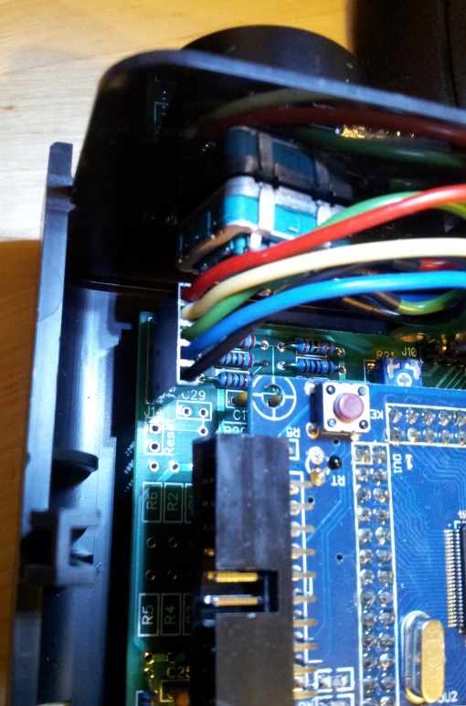
The board should now look like this:

Note that the diode D6 is not placed. It was meant to supply the device via
USB, but then the power switch would be somewhat pointless.
The potentiometer R21 is used to set the LCD contrast.
For the rotary encoder (Bourns PEC16 2215F-S002), a special cable is needed
which is then connected to J6 on the PCB.
The pinning is as follows (looking at the rotary encoder, pins pointing
down):
| 1 |
A |
red |
| 2 |
B |
yellow |
| 3 |
D |
green |
| 4 |
C (GND) |
blue |
| 5 |
E (GND) |
black |


To connect the CAN and UART box headers to the back plate, you need to build
to cables like that:

Note that the polarization bump of the female header on the right is
pointing left (towards the Sub-D connector).
Fully assembled unit:

Back to main page